
In This Article
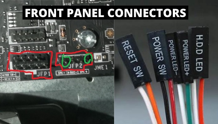
What Are Front Panel Connectors?
The front panel connectors signify the set of connectors that are found on the motherboard which are connected to the computer case.
Technically, these particular panel connectors refer to those that control the power button, the reset button and the LEDs through color coded cables.
KEY TAKEAWAYS
- The front panel connectors come with several pins each to serve a specific purpose which includes controlling the power and reset button, the LEDs and even the speaker that emits a beep sound on startup.
- All motherboards come with these connectors that connect to the case of the computer and may or may not come with a block encasing them.
- Known by different names, the system panel headers perform some primary and secondary functions of which the most significant is to act as the channel between the system and the motherboard helping them both to interact with each other.
- Different pins in the cables of these connectors serve different purposes and therefore it is needed to maintain the right orientation of it, especially those that connect to the different LED indicators.
- The system panel connectors can even help to jump start the motherboard if there is no power on button in the computer case.
Understanding Front Panel Connectors
All motherboards come with front panel connectors that are directly connected to them to establish a connection to the power and reset buttons on the computer case through cable.
However, there are a few specific manufacturers of motherboards such as ASUS who design their product with a Q-Connector.
This type of connector helps the users to connect the system panel connector cables to it first and away from the motherboard and then connect it to the motherboard.
These connectors are also known by different name such as:
- Front Panel Header
- F_Panel
- System Panel Connectors and
- System Panel Header.
The cables of these connectors typically come with two wires.
These cables and wires are color coded which helps in identifying them easily and to connect them correctly to the system panel connectors of the motherboard.
The wires colored black or white are the ground wires and others are typically the power wires.
All cables of the computer case are required to be connected to the right pins to function properly.
These cables usually come with the PC case itself. It may not come with all the cables because there is usually no need to populate all the pins of the system panel connectors.
The cables, connections, and colors may vary according to the type of motherboard and the computer case.
For example, the PC case may not come with a beep code speaker and therefore may not have a specific cable dedicated for that.
In the same way, the case may not come with a Chassis Intrusion sensor and therefore it may not come with the Chassis Intrusion or +CL pins or cables in it.
You can easily locate the system panel headers by using two specific methods such as:
- By using the manual of the motherboard that contains the full diagram of them describing the locations of the different slots, sockets, connectors on the motherboard and
- By physically reading the labels that you will find beside the sockets and connectors on the motherboard.
There are several small pins in these system panel connectors each of which serve a particular electrical purpose.
For example, there are two specific pins in the cable that connect and supply the power to the power switch located on the computer case.
In the same way, there are also two specific pins for the reset switch.
The two specific ways mentioned above will also let you figure out which particular pin of the different connectors serve which particular purpose.
This will prevent any confusions resulting due to some unique connectors that may be on the motherboard.
For example, apart from the typical functions, the connectors may also have some particular pins that are designed for serving some specific purposes such as:
- + MSG pin is dedicated for the Message LED indicates the power status which is also called the Power or Sleep LED and is usually yellow or purple colored LEDs
- + CL pin is dedicated for the Chassis Intrusion Header and is a gray colored LED that detects whether or not the computer cover is removed provided the PC case comes with a particular Chassis Intrusion sensor in the first place.
The orientation of these connectors and cables is very important, especially those that control the LEDs.
This means that you will need to make sure that the positive terminal of the cable is connected to the positive pins of the front panel connectors and the negative terminal is connected to the negative pin.
However, for the power and reset buttons, the cable orientation does not matter much.
Types of Front Panel Connectors
Based on the different types of LEDs and cable used, in general, there are five different types of F_Panels such as HDD, power, reset switch, power switch and speaker.
Here is a brief description of each of these different types of connectors:
- HDD LED – Also known as the IDE LED, these are the activity lights dedicated for the hard drives and flashes when information is read from and written to the hard drive.
- PLED – Also known as Power LED, these lights indicate whether the computer system is switched on, switched off or in standby mode.
- PWRSW – This is also referred to as the Power SW and is dedicated for controlling the power button that is used to switch on or switch off the computer.
- Reset SW – This handles the reset button of the computer system to restart it.
- Speaker – This is the internal speaker that produces a beep sound when the computer system boots up.
What Do These Connectors Do?
The system panel connectors are designed to perform different functions, both primary and secondary which include indicating the power status, controlling reset buttons and more.
As said earlier, the five primary functions performed by them are:
- As power switch controller with 2 pins to the power cable dedicated for it
- As reset switch controller with another pair of pins dedicated for it
- As power LED connection with 3 pins to connect to the LED lights on the computer case
- As hard disk LED activity indicator with two dedicated pins for it and
- As the beep code speaker connectors with 4 pins exclusively used for it.
In addition to the above, there are also a few other specific functions performed by the front panel headers.
One of the most notable functions is that these connectors allow jump start the motherboard in the absence of a power on button.
It can be done by touching both the pins of the power on switch together by using a precision screwdriver.
Are Front Panel Connectors Necessary?
The front panel headers are quite important because they allow you to integrate the PC chassis or case into the computer. These are the primary conduits to interact with the motherboard.
These connectors connecting the beep code speaker, which is very much different from the stereo speakers, helps a lot in troubleshooting.
The speakers emit different number of beeps and each of them indicates a specific problem such as:
- A single beep indicates that there is an issue with the system RAM or Random Access Memory
- If it beeps for four times it indicates that there is an issue with the motherboard of the system
- Five 5 beeps by it signifies a problem with the CPU or the Central Processing unit of the computer and so on.
The connectors are essential for a computer system to connect the motherboard and act as power on/off buttons for the system case.
Conclusion
Most users feel that the front panel connectors are trivial but after reading this article you will not, because you know what these connectors are and what roles they play.
The connectors act as the main channel through which the buttons on the computer case and the system communicate with the on-board motherboard.