What is IDC (Insulation Displacement Connector)?
IDC is the short form for Insulation Displacement Connector, which refers to the contact found typically at the ends of the cables. In this connection process, the blades cut through the insulation eliminating the need to expose the conductors.
Technically, an IDC signifies the electrical connector designed to connect the conductors available in the insulated cable through the insulation using a carefully sharpened blade or blades that are cold-welded to the conductor.
Understanding IDC (Insulation Displacement Connector)
The Insulation Displacement Connector is a specially designed wire-to-board connector that comes with judiciously selected sharpened blades that cut through the insulation of the conductors.
This helps in establishing a quicker and easier contact that is more secure, robust, and reliable.
In theory, the IDCs are pretty reliable, gas tight connector technology that is designed on the crimp and wire-wrap connector technology.
Initially, it could only connect single-stranded, solid connectors, but later on, its design was modified to allow it to connect multi-stranded wires as well.
In simple terms, the ribbon cables found in the hard drives, floppy disk drives, and Integrated Drive Electronic or IDE disk drives all have IDCs.
The IDCs are known by different names such as:
- Insulation Displacement Contact
- Insulation Piercing Contact (IPC)
Typically, a ribbon cable is designed to be used with IDCs with multiple contacts.
This allows making several IDC connections at the same time and is usable in situations where multiple connections are required, thereby saving time.
The ribbon cable is pushed into the flat, metallic contact that has a slight angle at the upper region to detect the wire correctly.
There is also a U-shaped lower region that cuts through the insulation and compresses the conductor.
Usually, from the IDC perspective, the terminals nibble through the insulation. In addition to that, it also exerts momentous pressure on the wire, creating a cold weld.
It is very easy and quick to make such a connection because it does not need stripping the insulation, twisting the wires and screwing down the connection.
It is pretty reliable as well. There is also a strain relief mechanism to hold the wire firmly in place. This reduces the chances of damage caused to the connectors due to strain and flexing and improves their reliability.
Design
The IDC connector technology is quite improved and works well due to the design and selective assembly process that generates a metal-to-metal contact.
Ideally, the connector stays mechanically stable, which results in further improvement in the joint due to supplementary diffusion welding as time progresses.
However, this mechanical stability depends on a number of factors such as:
- The spring properties of the connection and the terminal
- The strain and loading put on the wire
Typically, both of these factors are improved by the better design of the ID connectors.
Due to the relief from external strain on the cable, the reliability of the joint is further enhanced in the long term.
It is because there is adequate protection against movement at the interface of the wire terminal.
These specific connectors are usually characterized on the basis of specific parameters such as:
- The number of pins in them
- The number of rows
- The spacing or pitch (measured usually in mm) in between the pins
Also, the wires included in the design have a significant effect on its performance and reliability.
This is because the cable, such as the ribbon cable, comes with multiple strands, which offers the best performance.
The strand bundle does not experience compressive load, and therefore, it does not tend to lower contact forces by relaxing in the slot, thereby creating notable issues such as:
- Stress relaxation
- Mechanical disturbances
- Creep
These are also the effects of several other conditions such as:
- The number of layers and twists of the strands in the wire
- The top plating of the conductor
- The type of insulation
Alternatively, if a solid wire is used, there will be much better connectivity, but it may not be a robust one in the first place.
Therefore, it is the multi-stranded ribbon cables that deliver the best performance.
What is the Use of IDC?
Just as the name implies, an Insulation Displacement Connector is used to connect to the conductors of an insulated cable by cutting through the insulation with its specially designed blades.
Though it was initially designed to be used in ultra-low voltage applications only, over time it has been used in several other applications as well, which include but are not limited to:
- Different parts of a computer system or an electronic device
- Telecommunications
- Networking and signal connections
- Domestic applications
- Industrial power and other low voltage applications
- Keystone jacks
- Field termination plugs
- Patch panels
- ATMs
- Irrigation equipment
- Pumps
- Motors
- Security systems
- Automotive safety systems
- Solid-state lighting
- Solar energy
Talking about computers, there are several different components in which the manufacturers include a female IDC, where one end of the ribbon cable is to be attached.
This slides the connector later on to the corresponding pin header or male box header found on the computer motherboard.
Some of these computer components are:
- 5-inch IDE desktop computer hard disk drives that come with a pin configuration of 2.54 mm pitch and 40 pins (2 rows of 20 pins)
- 5-inch IDE notebook computer hard disk drives that come with a pin configuration of 2 mm pitch and 44 pins (2 rows of 22 pins)
- SCSI 8-bit drives that come with a pin configuration of 2.54 mm pitch and 50 pins (2 rows of 25 pins)
- SCSI 16-bit devices that come with a pin configuration of 1.27 mm pitch and 68 pins (2 rows of 34 pins)
- Floppy disk that come with a pin configuration of 2.54 mm pitch and 34 pins (2 rows of 17 pins)
- Serial DE-9 on motherboards that come with a pin configuration of 2.54 mm pitch and 10 pins (2 rows of 5 pins)
- Parallel DB-25 that come with a pin configuration of 2.54 mm pitch and 26 pins (2 rows of 13 pins)
Sometimes, the USB through version 2 on the motherboards that come with a pin configuration of 2.54 mm pitch, 10 pins (2 rows of 5 pins) may also come with Insulation Displacement Connectors.
IDC Types
There are basically two main types of Insulation Displacement Connectors namely, Ribbon Cable and Punch-down blocks.
- Ribbon cable – These IDCs are more widely used, especially in computers and their allied boards. This is mainly because the design of the ribbon cables allows connecting all the wires at once to the connector. It can be used in a diverse range of interfaces with their two rows of pin connectors.
- Punch-down blocks – Used mainly in telephone and network connectors, such as in Private Branch Exchange (PBX), distribution frames and patch panels, these specific blocks are designed to connect distinct conductors by punching down into separate positions in the block.
Read Also: What is Wireless LAN? Works, Pros & Cons
How to Use IDC?
In order to use the Insulation Displacement Connector just as it should be, apart from choosing the right type of IDC, you will also need to use the right tool and cable.
You can use a ribbon cable or a punch-down block, but along with them, you will also need to use a specially designed insertion tool such as a crimp tool and a punch-down tool, respectively, for connecting the wires easily.
A termination tool is also necessary for easy removal of the connecting wires.
At this point, you should know what to look for in the cable, in particular. The pitch is the biggest factor that would affect the performance significantly.
Ideally, if the connector comes with two rows, the pitch of the cable needs to be half. The main reason behind this is that these types of IDCs usually come with staggered pins.
Here is the summary of the pitch you should use for different connector pitches:
- For a .079″ (2.00 mm) connector pitch, the cable pitch should be .039″ (1.00 mm).
- For a .098″ (2.50mm) connector pitch, the cable pitch should be .049″ (1.25mm).
- For a .100″ (2.54mm) connector pitch, the cable pitch should be .050″ (1.27mm).
On the other hand, if you are using a single row cable, then the pitch of the connector and the cable can be the same. This will make using the connector much easier and more convenient.
However, whatever the number of rows in the connector is, it should be of the proper pitch. You should ideally look at the manufacturer’s datasheet to be sure.
Also, you should make sure that the orientation of the cable and connectors is correct, depending on the pin layout.
IDC Pinout
The pinout of the Insulation Displacement Connectors can be different, typically depending on the number of pins, which can be a 10-pin, 20-pin, or even a 50-pin IDC connector.
The position of the Pin 1 is usually “V” marked, and all of them are usually numbered from the first pin, with odd numbers on one side and even numbers on the other.
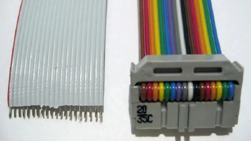
Usually, the Pin 1 is easily identifiable due to the red or raised V mark, but there are some specific types of ribbon connectors that come in multiple colors, with each of them representing a typical coding scheme for the wire numbers. For example:
- The brown color indicates Pin 1.
- Red indicates pin 2.
- Orange represents Pin 3.
- Yellow indicates Pin 4.
- Green signifies pin 5, and so on.
On other types of cables, there may be just a line down, adjacent to the first conductor.
As on the connector, Pin 2 will be opposite Pin 1, Pin 3 will be placed next to Pin 1 along the length of it, and so on.
As on the cable, the wire connecting Pin 2 will be next to the wire connecting Pin 1, and so on.
What Gauge is IDC Cable?
Usually, there are two common gauges of the ribbon cables used with the Insulation Displacement Connectors namely, AWG 26 or AWG 28, with sufficient and different current capacity for each for most applications. However, sometimes it may be 24 AWG or 22 AWG.
Typically, the gauge number is inversely proportional to the wire size or its cross-section area.
According to AWG, or American Wire Gauge, for a decrease in the gauge number by 3 points, the cross-sectional area of the wire is doubled. This increases the current capacity of the wire.
Usually, a slash separates the AWG size and the number of strands. For example, a 26 AWG 7/34 stranded wire indicates that the wire gauge is 26, and there are seven strands in it of 34-gauge wire.
Read Also: What is Expansion Slot? Function, Uses & More
As complex as it is, the gauge of the AWG wire sizes indicates the sizes as well as the electrical properties of the wires.
For your better understanding, here are the AWG wire sizes used in the most common ribbon cable summarized:
- The AWG 22 with a stranding scheme of 7/30 will have a diameter of 0.0253 inch or 0.644 mm, a wire resistance of 52.96 mΩ/m or 16.14 mΩ/ft in each strand of diameter 0.25 mm, and a maximum current for chassis wiring of 7 amperes and a fusing current of 41 amperes.
- The AWG 24 with a stranding scheme of 7/32 will have a diameter of 0.0201 inch or 0.511 mm, a wire resistance of 84.22 mΩ/m or 25.67 mΩ/ft in each strand of diameter 0.20 mm, and a maximum current for chassis wiring of 3.5 amperes and a fusing current of 29 amperes.
- The AWG 26 with a stranding scheme of 7/34 will have a diameter of 0.0159 inch or 0.405 mm, a wire resistance of 133.9 mΩ/m or 40.81 mΩ/ft in each strand of diameter 0.15 mm, and a maximum current for chassis wiring of 2.2 amperes and a fusing current of 20 amperes.
- The AWG 28 with a stranding scheme of 7/36 will have a diameter of 0.0126 inch or 0.321 mm, a wire resistance of 212.9 mΩ/m or 64.9 mΩ/ft in each strand of diameter 0.12 mm, and a maximum current for chassis wiring of 1.4 amperes and a fusing current of 14 amperes.
Therefore, you can see that, among other factors, the cross-section area, or AWG, has a significant effect on the maximum current capacity of the flat ribbon cable.
Of course, the operating current is always much lower than the fusing current.
How to Install IDC?
You can install the Insulation Displacement Connectors using standard tools and following specific methods.
The process is simple, but you will need to align the wires in the right slots.
The steps to follow are:
- First, you will have to slide the ribbon cable through the connector. Make sure that you slide it a couple of inches down the connector.
- Squeeze the connector and pull the cable back so that the connector moves to the end of the cable. Make sure that the wires on the cable align with the proper slots on the connector.
- Now, simply press the connector firmly together, and it is ready for use.
- Put the strain relief on either end and you have a highly flexible IDC.
IDC Vs Crimp Connector
- IDCs are much easier to make connections with and remove the wires from the contacts in comparison to the crimp connectors.
- Using the IDC connectors saves a lot of time and effort as compared to using the crimp connectors.
- The IDCs allow easy removal of wires, resulting in little or no wire deformation. On the other hand, in a crimp connector the pre-stripped terminal and wire can be deformed due to high pressure crimping dies used to attain metal to metal contact.
- In the case of the IDCs, it is easy to achieve a cold weld, but in comparison, in the case of crimping, achieving cold weld is a critical factor.
- The Insulation Displacement Connectors are much more reliable and robust in comparison to the crimp connectors.
Conclusion
So, through this article you now know that the Insulation Displacement Connectors are reliable connection solutions, which are a good alternative to crimping.
The connectors create simultaneous contact with all of the conductors via a gas-tight interface without needing to strip the insulation on the wires.