What is Integrated Drive Electronics (IDE)?
Integrated Drive Electronics or IDE refers to a specific technology and an electronic interface standard. This typically helps in connecting the disk storage devices and the motherboard of a computer.
Originally, this interface followed the 16-bit bus standard of the IBM PC Industry Standard Architecture but later on other bus standards were also implemented.
Understanding Integrated Drive Electronics (IDE)
Integrated Drive Electronics or IDE is known by myriad names such as ATA, IDE/ATA, EIDE, and more.
It is also classified on the basis of its average data transfer speed of 100 MB/s but the most common name by which it is known is ATA or PATA, a short for Advanced Technology Attachment and Parallel ATA respectively.
Initially, this referred to the standard interface of the IBM computers first developed in 1986 by Western Digital and Compaq to connect compatible CD, DVD and hard drives.
You should not mix up an IDE with the SCSI or Small Computer System Interface and ESDI or Enhanced Small Disk Interface.
The most significant feature of the Electronic Drive interface that sets it apart from the SCSI and ESDI is that the controllers of it are in each drive.
These controllers were separate external devices before IDE. This means that the drives can connect to the controller or to the motherboard directly.
The main benefit of having the disks and the controller in the same device instead of separate ones is that the distance of the two is reduced and this has a significant positive effect on the performance.
The IDE devices are cost effective and come with their own circuitry to reduce issues related to both storage devices and controllers.
Most of the computers come with CD-ROM or hard drive connections where the hard drives have one cable to connect to the motherboard using the main Intelligent Drive Electronics connector. The other drives and storage devices usually share an IDE cable.
Read Also: What is VRM (Voltage Regulator Module)? (Explained)
In a regular ATA/ATAPI interface, there are two separate connectors such as the IDE/ATA cable which is used to connect the devices to the data connector and the regular power connector that supplies the necessary power.
IDE is used extensively today in comparison to SCSI and others because it is quite inexpensive, much simpler, and equally fast.
However, the hard disk needs to be compatible with the IDE controller and vice versa for using it and for its proper functioning.
Usually, the motherboards come with one of these interfaces to allow connecting two drives to a computer but there are several modern motherboards that offer two such interfaces, one primary and one secondary to allow connecting four drives at a time.
There are different versions or standards of ATA available to match with the new and evolving technologies such as:
ATA 1 – This is the first IDE standard that had a 40 or 44 pin connector. It defined both multiword DMA mode 0 and PIO or Programmed Input Output modes 0, 1 and 2.
ATA 2 – This is also known as EIDE or Enhanced IDE which had additional PIO modes 3 and 4 along with DMA modes 1 and 2 and supported devices other than hard disks with increased storage capacities and speeds.
ATA 3 – This improved version came with features like more reliability, higher data transfer speed, analysis and reporting technology, self-monitoring feature, and password protection to prevent unauthorized drive access.
ATA/ATAPI 4 – Also called the Ultra DMA/33 this particular version came with additional ATAPI or ATA Packet Interface to support other device types such as tape systems and CD-ROM.
It also supported data transfer speed of up to 33 megabytes per second, an 80-pin conductor and a 40-pin ribbon cable.
ATA/ATAPI 5 – This standard is also known as Ultra ATA/66 due to its improved data transfer speed of up to 66 megabytes per second using an 80-conductor cable.
ATA/ATAPI 6 – Providing support to Ultra DMA/100, this standard can transfer data at a speed of up to 100 megabytes per second and included features such as Automatic Acoustic Management that allowed the drives to adjust the access speed automatically to trim down running noise.
ATA/ATAPI 7 – SATA was introduced in this standard that allowed transferring data at a speed of up to 150 megabytes per second for SATA drives and 133 megabytes per second for PATA drives.
It used a ribbon cable and a 7-pin connector to attach the SATA drives. This standard was divided into three volumes where the first defined the register delivered commands used by the devices, the second focused on PATA and the third volume dealt with SATA.
ATA/ATAPI 8 – Built on the previous version, this includes SATA 2.x and 3.x and offers a transfer rate of up to 600 megabytes per second for SATA and 133 megabytes per second for PATA.
It also comes with other revisions for both PATA and SATA along with latest flash-based Solid State Drive capabilities.
Over the years, the 20 megabytes storage offered initially grew to hundreds making IDE the most commonly used standard of today.
How Does IDE Work?
The basic principle followed in the working process of the IDE is that the controller and the hard drive are combined. The IDE interface found in the computers and built onto the motherboard uses a 40-pin connector usually to attach the drives and work.
The working process of it can be described as follows:
- A signal is sent by the IDE interface when a computer is switched on through the wire for Pin 28
- This signal is received by only that specific drive which is attached to the master connector
- The drive then configures itself to perform as the master drive and the other drive that does not receive the signal functions in the slave mode by default
- It uses a special configuration referred to as master and slave where the controller of one drive tells the other when it can transfer the data to or from the computer
- A request is made by the slave drive to the master drive
- The master drive checks whether or not it is communicating with the computer system currently
- If it is idle the slave drive goes ahead with the process and if not the master drive tells it to wait till the time it gives the signal to go ahead and
- The computer checks for the availability of a second slave drive connected to it through Pin 39 on the connector using a special signal sent through this pin called DASP or Drive Active/Slave Present.
While transferring data through the interface, the controller integrated into it sends a range of blocks of 512 bytes between the drive connected and the motherboard.
This controller is actually a small circuit board that comes with several dedicated chips and controls and guides the hard drives as to how exactly they should store and allow access to the data.
IDE Examples
There are different IDE standards developed and released right from ATA I released in 1984 and ATA 8 till date, each with different data transfer speeds and other characteristics.
The first IDE standard was called the ATA-1 and was released in 1994. It supported transferring data in DMA or Direct Memory Access mode at a speed of up to 8.3 MB/s.
It was further improved to create the Enhanced IDE or ATA-2 released in 1996 which can transfer data at a rate up to 16.7 MB/s, twice that of the original.
The next IDE versions or standards were released over time till ATA 8 with a maximum data transfer speed of 133 MB/s.
The IDE interface however was superseded eventually by SATA which is even a faster interface.
What Are the IDE Connectors?
The IDE connectors refer to the standard interface that connects the motherboard of a computer to different storage devices such as DVD or CD-ROM drives.
Read Also: What is Power on Self Test (POST)? (Explained)
There was a 16-bit interface in the original IDE to connect two devices with a single ribbon cable but over time two types of connectors became more common. These are:
- The 34-pin connector for floppy drives and
- The 40-pin connector for optical drives and hard drives.
Later on, 80-pin connectors were also introduced.
The 40-pin connectors come with a ribbon cable attached to it, just like the others, and are usually black in color. The 80-pin connectors, on the other hand, come in three different colors that indicate their different purposes such as:
- Blue for controller
- Gray for slave drive and
- Black for master drive.
If you consider the PATA and SATA connectors, they both differ in maximum data transfer speeds ranging anywhere between 133 MB/s and 1969 MB/s respectively.
Questions & Answers:
What is IDE Used For?
The IDE, as said earlier, is used as a standard interface to connect different storage devices such as hard drives and other optical drives to the motherboard. The main objective to create it was to even out the use of hard drives in computers.
How Many Devices can be in an IDE Interface?
Typically, if there is only one interface in your computer system, it will support up to two devices. There will be three connections in the ribbon cable, one to connect to the motherboard and the two others to connect the two drives.
However, most of the modern motherboards usually come with two IDE interfaces, one primary and one secondary. This allows the users to connect as many as four IDE devices.
What is Meant by No IDE Device?
As you may know, the BIOS or Basic Input Output System of a computer scans the memory when you start the system to check the video adapters before it looks in the hard drives for a bootable operating system. If the hard drive has failed or is incorrectly configured, there will be a ‘No primary IDE found’ error. It will stop the startup process.
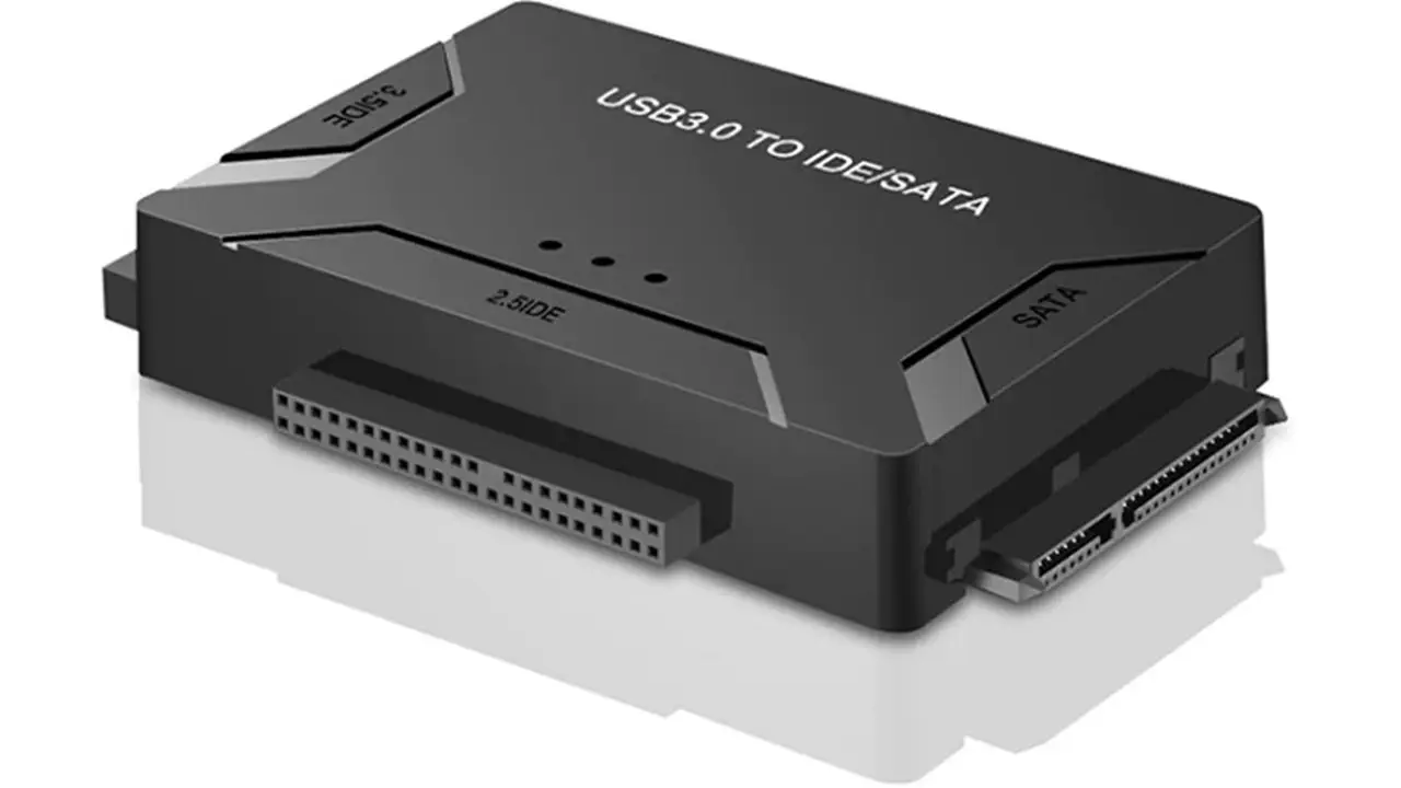
Is There USB in the IDE?
You will need to use a SATA/IDE-USB adapter that typically comes with three interfaces to one USB adapter. This will allow you to connect almost all types of drive to your computer through the USB such as SATA, 2.5-inch IDE, 3.5-inch IDE, and 5.25-inch IDE and even hot-swap them easily.
Conclusion
So, after going through this article now you know that IDE plays a significant role in computing by offering an interface that offers support to the Hard Disk Drives with integrated controllers.
The development and use of this interface has reduced the issues in storage devices and controllers and data transfer speed.