 Bus")
In This Article
What is I2C (Inter Integrated Circuit)?
I2C or Inter Integrated Circuit refers to the bus technology designed by Philips which allows connecting a large number of low cost and older peripherals to the motherboard of a computer system or other embedded systems.
Technically, IIC bus interface protocol allows serial communication for a short distance with just two wires, which is why it is also called a Two Wired Interface or TWI.
KEY TAKEAWAYS
- Designed by Philips in the 1980s, the I2C bus allows easy connection and communication between the parts that reside on the same circuit board.
- Also referred to as Inter IC, IIC or I²C, this bus initially operated at a very low speed of 100 Kbit/s. The later versions however accomplished higher speeds of 400 Kbit/s in the fast mode and 3.4 Mbit/s in high speed mode.
- Fast mode plus and Ultra Fast Mode variants are also available that can transfer data at a higher speeds but these are honestly not real I2C buses.
- This particular interface comes with only two wires that support data line and serial clock and allows connecting multiple devices.
- IIC is used on single boards and it is the flexibility and simplicity of it that makes it such an attractive bus for several applications.
Understanding I2C (Inter Integrated Circuit) Bus
I2C interface is a bus protocol that is also known as IIC, I2C, Inter Integrated Circuit and even TWI or Two Wire Interface due to the presence of two wires in it.
It allows serial communications between the connected devices but is typically used for the sensors and modules but not for communicating between any device and the computer.
The design of the IIC bus resembles a simple, bidirectional, synchronous and dual wire serial bus and allows connecting several low cost devices to the motherboard.
The messages sent are typically broken into two specific types of frames such as:
- An address frame and
- One or more data frames.
Here the address frame is utilized by the controller to indicate which peripheral the message is being sent and the data frames consist of 8 bits of data messages that are transferred by the controller to the peripheral device or vice versa.
In this bus the data is sampled when the SCL line is high and is placed on the SDA line if the SCL is low.
The time between read/write data and the clock edge is determined by the devices connected to the bus but may vary from one chip to another.
The reading and writing operations from and to the slave device on the IIC bus are also quite unique.
While writing, the master sends the START condition with the slave address and the last read/write bit set to 0.
This signifies a write operation is to be conducted. The register address to which data is to be written is send by the master device only when the slave device sends the acknowledgement bit.
When the slave sends the acknowledgement bit once again, the register data is then sent to it by the master device and will send the STOP signal to terminate the transfer.
The reading process is much similar to the writing process but there are a few additional steps to follow.
Once the register address is acknowledged by the slave device, the master device again sends a START condition and the slave address but the read/write bit is now set to 1 which signifies a read operation is to be conducted.
When the slave acknowledges it, the master device allows the slave device to use the SDA bus to send data but continues to supply the clock pulses to the slave.
At this particular stage of the process, the master device becomes the master-receiver and the slave device becomes the slave-transmitter.
The master device sends an acknowledgement to the slave device after receiving every byte of data to let the slave know that it is ready to take on more data.
Once the desired amount of data is received, the master will send a No Acknowledgement bit to the slave to end the transmission and release the bus.
This is followed up by the master device by sending the STOP condition finally.
How Does I2C Bus Work?
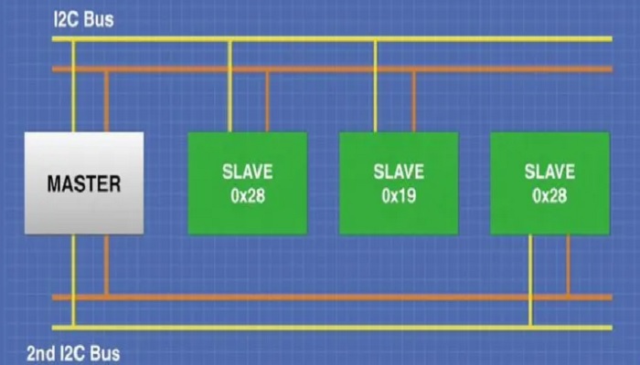
This bus actually connects the devices to a set of two wires and then allows communicating with each of them individually, specifically between the master and slave device.
The two active wires in the IIC multi master bus namely Serial Clock/SCL and Serial Data/SDA helps it to work and transfer data bit by bit through each of these wires.
The working process involves these following steps:
- The data is first sent to the Serial Data Line
- It is then synchronized by the Serial Clock Line with the clock signal
- A 7-bit address is assigned by the master to the slave device on the SDA line
- The data is then transferred in messages and are broken into several data frames
- The slave is informed that data is being sent with the START issued by the master device
- Then the address of the device to be accessed is sent by the master device
- The slave device compares the address with its own address after receiving it and sends the ACKNOWLEDGE signal if it matches
- The master device then starts sending or receiving data after receiving the acknowledgement and
- When data transmission is completed, a STOP condition is issued by the master device.
However, if the address of the device does not match with that of the slave device, it will simply wait until the release of the bus by the STOP condition.
The data through this bus is usually transferred in the form of data packets that consist of 9 bits and these bits are sent in a specific sequence during different stages of operations. For example:
- During the START condition it consists of only 1 bit
- The slave address typically contains 8 bits of data and
- Acknowledgement is sent in a single bit.
However, for the I2C bus to work properly, it needs more complex hardware than SPI but not as complicated as it is in asynchronous serial.
Where is It Used?
Inter IC bus is used to connect a large number of peripheral devices in an embedded system such as microcontrollers, Input/Output interfaces, EEPROM or Electrically Erasable Programmable Read-only Memory, and others as slave devices.
This specific protocol is also used to communicate between two or more Integrated Circuits which is why it gets its name Inter Integrated Circuit.
These two ICs may be situated on the same Printed Circuit Board or PCB.
Several entry-level and mid-level embedded systems also use this bus protocol to establish short distance communication even within the same device or board.
Some other significant uses of this bus include:
- Defining connectable devices such as Serial Presence Detect or SPD ROMs, Dual In-Line Memory Modules or DIMMs and Extended Display Identification Data or EDID for monitors with small ROM configuration tables that enables plug and play operation
- Better system management through SMBus
- Accessing RTC and NVRAM chips and low speed Analog to Digital Converters or ADCs and Digital to Analog Converters or DACs
- Changing monitor settings such as hue, contrast, color balance and backlight through Display Data Channel
- Changing volume of intelligent speakers
- Controlling small LCD and OLED displays as found in mobile phones
- Turning power supply on or off and
- Reading diagnostic sensors and hardware monitors.
The two bidirectional wires transmit and receive information facilitating a serial communication only which is especially useful for master-slave configurations and multiple peripheral ICs.
Features of I2C Bus
Simplicity and flexibility are the most significant features of the I2C that are worth mentioning and have made it so popular. It comes with only two wires but allows connecting a large number of devices supporting variable data speeds.
Some of the other significant features of this bus include:
- Collision detection
- No stringent baud rate requirements
- Simple master/slave relationship
- Software addressability of devices with the help of a unique address
- Multi-master support
- Arbitration provision
- Data broadcast
- 10-bit addressing and
- A low pin or signal count.
It also comes with a much better mechanism to handle errors such as ACK/NACK or Acknowledgement/No Acknowledgement feature.
Apart from that, the bus protocol offers higher adaptability that enables it to work with both slow and fast Integrated Circuits or ICs.
Typically, the Inter IC uses a shared bus and an address system which allows connecting such a large number of devices to it through the same wires.
Data can be transmitted through a single wire with a low pin count. However, this makes this bus slower.
The working of this bus is typically initiated, controlled, and terminated by the master device mainly as well as the serial clock line and the serial data line. This allows synchronizing transmission.
Apart from that, a constant power supply is also required for its working which is maintained by the pull up resistor that it is connected to.
Depending on the conditions available, the bus transmits data in different modes which also determines its speed of operation such as slow mode, quick mode and high speed mode.
Is I2C Bus Faster than USB?
There is no doubt that the USB is much faster than I2C and comes with a much wider range of operating speed. The maximum speed of I2C can be up to 3.4 MB/s in the embedded systems and a high of 400 Kbit/s in others.
However, in comparison, the USB 3.0 can operate at a speed of up to 4.8 GB/s.
The most significant factor that makes the Universal Serial Bus or USB much faster than the I2C is that it is based on differential signaling while the latter is a ground referenced bus.
Another major factor for the I2C to operate at a lower speed is that it normally uses a 400 KHz clock but, in comparison, the USB 1 and 2 use 12 MHz or 120 MHz clocks.
Though the clocks are general rates and are not fixed, faster data clocks typically mean faster output.
Also, it is the drive mode of the data or clock lines that results in the difference in the speeds of these two particular bus types.
Typically, I2C uses an open-drain drive mode for the clock and data lines but the USB uses a strong drive mode.
The design and features of the two respective buses also affects the eventual operating speed. I2C is typically designed to be a cheap alternative interface for providing external control to the cheaper parts.
That is why you can use a large number of devices with this bus.
This however means that you will have a hard time to match the impedance and terminations as such.
Therefore, you will have to wait for it to rise and to subside as the case may be, because this bus uses the same connector for different devices with the help of a pull up register on the PCB and open collector drivers.
This means that there is a RC constant between the capacitance and resistor of the signal which results in slower speed. And, since the slave clock can stretch the master, it needs to slow things down considerably.
The USB on the other hand, is a point to point bus and does not allow connecting multiple devices without using a router or any other active hardware.
This enables it to increase the bandwidth and the data transfer rate. It is not designed to be used as ad-hoc wiring like I2C for very low cost devices and therefore cannot be bit bashed.
With the use of proper hardware, USB can send data blocks of 512 bytes or 1024 bytes via USB 2 and USB 3 respectively.
It will send and receive buffers in a single packet which signifies that it has a much higher gate count for the buffers in comparison to the I2C bus.
This specific interface comes with hardware implemented handshaking and CRC or Cyclic Redundancy Check, which results in higher buffer gates and higher speeds than the I2C interface.
Is It Serial or Parallel?
Typically, I2C is considered to be serial because it supports serial communications protocol, much like UART or Universal Asynchronous Receiver/ Transmitter.
The multi-point protocol allows communication through the serial interface which is made up of a SDA or serial data line and a serial clock or SCL.
Moreover, this bus is considered to be synchronous which means that it functions on a serial clock which is driven typically by the master device.
This allows the bit outputs to be harmonized with the sampling of bits by the clock signal that is shared among the master and the slaves.
However, I2C is typically used for communicating between sensors and modules and not between the computer and the devices connected to it.
How Many Wires Do I2C Bus Have?
There are only two wires in an I2C bus but the surprising fact is that these two wires can support as many as 1008 slave or peripheral devices.
This sharing feature of this two-wire protocol makes this bus so incredibly popular to connect a large number of sensors, drivers, and expanders to communicate between them.
These two wires are responsible for sending and receiving data. At the physical level, one of the wires is connected to the serial clock pin or SCL to receive the pulses sent by the controller board. The other wire is connected to the SDA or serial data pin through which data is transferred between the two connected devices.
How Many Devices Can be Connected to It?
You can connect as many as 128 devices to an I2C bus. This is because the two wires in it can be shared by multiple devices which allow using a lot of sensors, expanders and drivers without even needing to use all of the available pins of the microcontroller.
Also, the fact that 7 bit number can be from 0 to 127 allows you to connect so many devices which however is limited only by the total bus capacitance allowed which is usually of 400 pF.
What is the Speed of an I2C Bus?
The speed of the I2C bus usually comes in different grades with the standard speed being 100 Kbit/s, full speed being 400 Kbit/s, fast mode being 1 Mbit/s, and high speed mode being 3.2 Mbit/s.
However, these all are maximum ratings and all will happen over a physical interface consisting of two wires, one for the serial clock or SCL and the other for data or SDA line.
This speed may vary a bit depending on the hardware compliance. For example, 8 bit serial and bidirectional data transfer can happen at a speed of up to 3.4MB/s and it can be up to as low as 10 Kbits/s.
Typically, the speed of I2C is low due to the fact that all the lines are open-collector and therefore the transmitter drives the line low only. This is opposed to SPI where the transmitter can drive both high and low lines resulting in a higher data transfer speed.
The speed of this bus also depends on other specific factors such as:
- The wire quality
- External noise and
- The speed of data itself.
Moreover, the use of a pull-up resistor by I2C sets a logic 1 limit which is why the speed of this bus is only 3.4 Mbit/s even at high mode.
The data transmission speed is also affected by the capacitance in the line.
If the current power is too small in the bus but the capacitance is very high, there will be errors in transmission.
Therefore, it should be about 400pF. This will allow estimating the number of devices to be connected to it and the length of the bus as well.
Questions & Answers:
I2C Bus Examples
The I2C is found in a wide range of chips and some of the examples include the DS1307 serial Real Time Clock or RTC module, SSD1306 OLED display and MCP23017 serial expander.
Is I2C Bus Input or Output?
Ideally, with the SDA and SCL in the I2C allows using this bus both as input and output at both 3.3 volts and 5 volts.
This makes it more usable and ideal to use as a level shifter chip for those particular peripherals that support 5 volts and are not compatible natively with the RPi's GPIO or General Purpose Input/Output ports that are typically of 3.3 volts.
Is I2C Bus Simplex or Duplex?
I2C is half duplex by default having just two wires but during communication it supports both multi master and multi slave support as opposed to single master support by SPI or Serial Peripheral Interface.
Conclusion
The I2C interface is very useful to connect multiple devices to the computer.
However, it can only be used for very low cost parts and operates at a significantly low speed as compared to any regular USB.
It comes with only two wires that can be shared by all the connected devices which make it quite a popular choice.