
In This Article
What is Parallel Port?
Parallel ports refer to a specific type of interface that was used in the earlier days to connect peripheral devices to the early computers. It is designed to send data in multiple bits in parallel or at once for communicating between the devices.
Technically, there are multiple data lines in the cables of these ports which is why these are larger than the cables and connectors of serial ports that need only one data line to send one data at a time.
KEY TAKEAWAYS
- Parallel ports were a very popular interface that were used to connect printers to the IBM compatible computers especially till the 2000s.
- These ports could transfer data at a much faster rate than a serial port because it transmitted data in 8 bits at a time using the parallel connection and the eight pin connectors.
- Parallel interfaces are installed onto the motherboard and are typically found at the back of the computer case and the connector had 25 pins that served different purposes during operation.
- There are different modes in which these ports could operate such as unidirectional, bidirectional and more.
- The need for higher speed and advanced data transmission requirements pushed these ports slowly after ruling the industry for about thirty years by the faster and more advanced USB, FireWire and network adapters.
Understanding Parallel Port
The parallel port is that interface that was originally known as Parallel Printer Adapter and was found typically on IBM compatible computers to connect printers that followed the 8-bit extended ASCII character set of IBM to print text.
However, it could also work with graphical printers and a host of other peripherals.
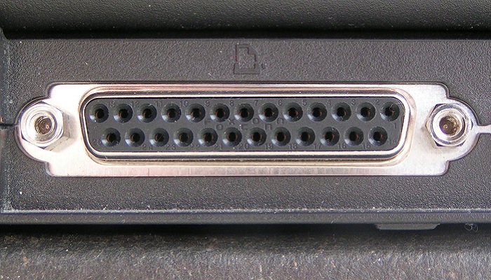
Less commonly known as Centronics ports, Centronics connectors, or Centronics interface, these ports typically come with a 25-pin configuration and are referred to as type DB 25.
It is quite easy to identify a DB 25 parallel port because it is usually the biggest connection that you will find at the back of the computer. The connection of this port looks like the letter D.
These ports can operate at different modes depending on the available resources and according to your need which include:
- IEEE 1284 or auto
- Centronics
- Nibble
- Bidirectional
- Unidirectional SPP
- EPP and
- ECP mode.
The bidirectional version of the parallel ports was standardized by the Institute of Electrical and Electronics Engineers or IEEE and was referred to as IEEE 1284.
This particular standard defined that this type of parallel communication allowed receiving and transmitting data bits between a computer and other peripheral devices.
This particular interface uses a parallel cable to transmit data which is typically no longer than 6 feet, the standard measurement, because a longer cable will result in issues and the data integrity may also be lost.
However, a few manufacturers recommend using a cable 10 feet long, maximum.
One bit of data is transferred by the parallel ports on each of the two wires which increase the DTR or Data Transfer Rate.
There are also supplementary wires available that regulate the signals to indicate when data is available for transmission or receiving.
It is very easy to identify these ports not only due to their larger size but also due to the fact that they are characterized typically by the dual row of small holes to accept the rows of pins on the connector.
The cord can be fastened to the computer securely with the screws on each side of it and the holes on the two sides of the port.
However, there is no universal standard for the connectors in spite of the commonalities in the interface.
Therefore, a variety of cables were available to use with the parallel ports such as:
- The DC 37 connectors
- 25 pin card edge connectors
- 36-pin ribbon connectors and
- The 50-pin micro ribbon connectors.
With the standardization of this interface, more devices started using a parallel interface apart from printers and scanners such as zip drives, webcams, external modems, gamepads and joysticks.
Even specific adapters were manufactured so that the SCSI devices could run on parallel ports.
Sadly, in spite of the tremendous and fast fruition of parallel communication, the parallel ports were replaced by the faster Universal Serial Bus or USB and Ethernet interfaces.
Most of the computer manufacturers today do not include this interface in their products anymore considering it to be a history in computer science and in the industry as well.
How Does Parallel Port Work?
The working of the parallel port is typically based on the available voltage on the respective pins. The computer determines whether the voltage or charge is steady in the pins or has dropped, which indicates something or the other as explained below.
When a printer is connected to a computer with the help of this port, data is sent to it by the computer. It sends 8 bits of data at a time, which is equal to 1 byte.
The data is sent parallel to each other and not in a single line or serially and at a speed ranging between 50 and 100 kilobytes per second if it is a standard parallel port.
Here is what each of the pin does when the interface is connected to a printer:
- The strobe signal is carried by Pin 1 at a steady voltage level between 2.8 volts and 5 volts and drops down below 0.5 volts when a byte of data is sent by the computer so that the printer is ready when the data is sent.
- Data bits are carried by the pins numbered 2 to 9 by sending 5 volts of charge through the right pin to signify that the bit value is 1. When there is no charge on a pin the value of the bit is supposed to be 0.
- The acknowledge signal is sent by Pin 10 from the printer to the computer system working just like Pin 1 by maintaining a steady voltage and dropping below 0.5 volts to tell the computer that it has received the data.
- The Pin 11 is charged if the printer is busy and the voltage will drop down below 0.5 volts to tell the computer system that it is now ready to receive the data bits.
- The Pin 12 is used by the printer to let the computer know that it has run out of paper or signal it that there is a paper jam in the printer.
- The device is supposed to be ready and online as long as the computer receives a charge or voltage on Pin 13.
- A 5 volt charge is used and sent through Pin 14 by the computer to indicate that the printer is ready for an auto feed.
- When the voltage of Pin 15 falls below 0.5 volts it indicates an error or a problem in the printer.
- A voltage drop in Pin 16 initializes the printer when a new job is ready
- A charge is sent through Pin 17 to take the printer offline as long as it is needed and
- The Pins 18 to 25 are grounds or data bit return.
Therefore, the 25 pins in the connector play a very important role during the data transmission process to make the parallel port work most efficiently.
Types of Parallel Port
Ideally, there are two major types of parallel ports namely the unidirectional 4-bit parallel ports and the bidirectional 8-bit parallel ports. However, there are also a few other types that may be classified according to the mode of operation.
The unidirectional 4-bit parallel ports were also referred to as Standard Parallel Port or SPP. This type was considered to be the de facto Centronics port standard.
It was included in all original IBM computers and their clones. The irony is, these ports are neither unidirectional nor are they restricted to 4-bit data transfers. They are capable of 8-bit output and 4-bit input both.
The SPP ports were extensively found in earlier desktop and laptop computers but are still found in a few low-end I/O cards. The native output of these ports is within the range of 40 KB/s to 60 KB/s but it can be pushed up to 150 KB/s with a few design tricks.
The bidirectional 8-bit parallel ports were included in the low cost models of the IBM PS/2 line and were designed to transmit 8 bits of data at the same time.
It not only could transfer data at a higher rate but also allow other peripheral devices such as keyboard and mouse other than printers to be connected to the computers.
There is also the Enhanced Parallel Port or EPP with expanded functionalities and capabilities available along with similar types of extended parallel ports.
These ports could transfer data at a high speed ranging from 500 KB/s to 2 MB/s, which is much higher than the traditional parallel ports and so was used in the newer printers and scanners.
Under the category of 8-bit bidirectional ports also comes the Expanded Capabilities Port or ECP which is similar to the EPP but uses Direct Memory Access mode.
It was used in disc drives, network adapters and other non-printer peripheral devices as well.
Typically, the earlier ports were limited in their functionalities, performance and capabilities in comparison to the newer variants of parallel ports that could be even configured to imitate the earlier ports when it needed to support older peripheral devices.
The computers, on the other hand, may be equipped with one of these types of parallel ports or more than one of them as well.
Uses of Parallel Port
A parallel interface is used mainly in personal computers to send and receive data to and from a peripheral device such as a printer through several bundled cables.
In addition to that, these ports were also used extensively in these following devices in its heydays:
- Scanners as an alternative to SCSI because these are easy to use
- Low end input-output cards
- External hard drives
- External modems
- Webcams
- Joysticks
- Gamepads
- Removable Iomega Zip drives which allowed removing from one PC and connecting to the other
- Network adapters
- CD burners and
- Tape backup drives.
The Apple Macintosh computers use the parallel SCSI that is more flexible as compared to the regular parallel ports that are used in the IBM compatible PCs. However, Apple computers have not used a parallel port ever.
Parallel Port Pins
There are altogether 25 pins in a parallel port. Eight of them are data pins, four are control pins, five of them are called status pins and 8 remaining pins are for ground.
As said earlier, the purpose of the different pins in this port is different and is as follows:
- Pin 1 is used for sending acknowledgement signals
- Pin 2 to Pin 9 are used to send data bits 0 to 7 respectively
- Pin 10 is used to send signals for the completion of process and when the printer is ready to take more
- Pin 11 is for acknowledging data receipt by the printer
- Pin 12 is to send signals paper issues in the printer
- Pin 13 is used for tell that the printer is online
- Pin 14 is meant to send signals for auto feed
- Pin 15 signals errors in the printer
- Pin 16 sends initializing signals
- Pin 17 sends signals to take the printer offline and
- Pin 18 to Pin 25 are used as ground pins.
Are Parallel Ports Still Used?
The parallel port, which is more closely related with the printer port, is hardly used today since it is replaced by Universal Serial Bus devices and computer network printing using printers connected to the system via Wi-Fi or Ethernet. Faster solutions such as FireWire and others have replaced it as well.
However, it was the de facto standard of the computer industry for a long time from the 1970s till the 2000s but is usually not found in modern computers.
This is because the devices are smaller in size these days leaving no room for these longer and legacy parallel interfaces to be installed.
Nonetheless, you can use a USB to parallel adapter to make the parallel-only printers compatible with the USB-only systems.
Also, there are Peripheral Component Interconnect and PCI Express cards that offer parallel ports.
Apart from that, you will also get a few specific types of print servers that come with an interface to parallel ports via a network.
Even the non-printer devices can work on modern computer systems with no parallel ports by using USB to EPP/ECP or Enhanced Parallel Port/Enhanced Capability Port chips.
In addition to that, the parallel ports are also often used by the electronics hobbyists even today since it is the easiest means to connect an old system they have and are fond of using to any external circuit board. The other reasons for them to favor a parallel port are:
- It is faster in comparison to other regular legacy ports such as serial port
- It does not need any serial to parallel converter
- It needs less interface logic and
- It needs less software in comparison to a USB specific interface.
Also, the present CNC Milling Machines use the parallel ports more often so that the attachment and motor of the machine can be controlled directly.
Questions & Answers:
Examples of Parallel Port
The most common parallel port is called the Centronics port and is used in the printer. These ports are also used in a floppy disk, early scanners and printers, early external circuit boards and docks, multiple radio versions, laplink cable, a few early speakers and more.
What is the Speed of Parallel Port?
Initially, the parallel ports could transfer data at the rate of 150 KB/s with one 8-bit data bus. However, the speed varied quite drastically depending on the type of device in question. For example, the parallel ports in the early scanners could transfer data only at a speed of up to 70 KB/s.
Where is the Parallel Port Located?
The parallel port is typically located at the back of the computer system because it is a part of the motherboard.
Conclusion
So, now you know that the parallel port, which is now replaced mostly by USB devices, was a very useful and extensively used point of contact especially for the printers with the IBM compatible computers.
Being faster than the serial ports, they ruled the industry for about three decades and were used in many devices.